Analysing Second Order System Response of an RLC Circuit
Analysing Second Order System Response of an RLC Circuit using Mathematica

This question was part of the Lecture Slides for Laplace Transforms of EN1060 taught by our lecturer Dr. Ranga Rodrigo. In this, I'll show the steps in solving it.
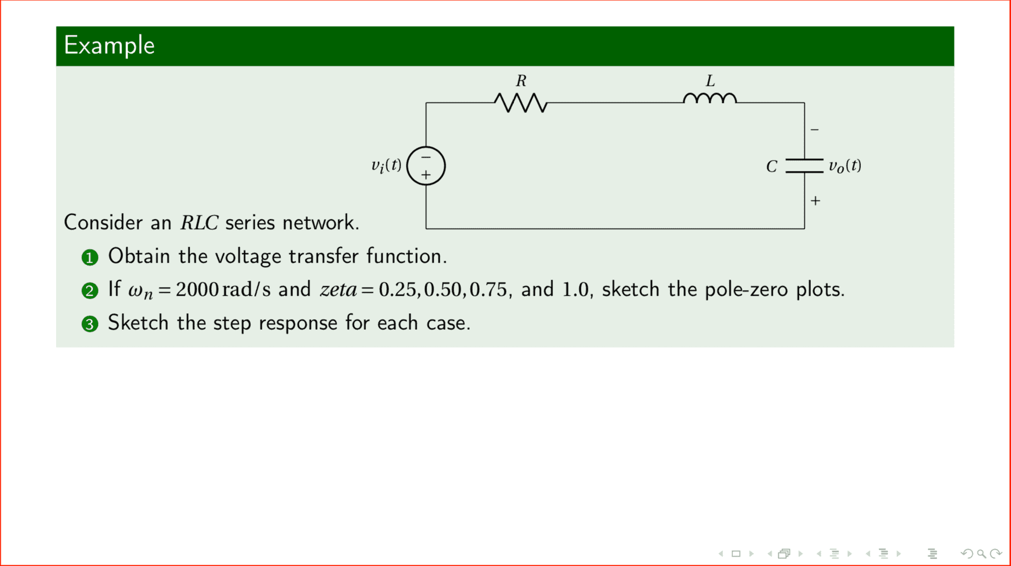
1) Obtaining the Transfer Function,
x(t) is the input voltage while the voltage across the capacitor is the output voltage y(t). So, Equating the sum of voltages across each component we get,
Examine the following code example,
Note that the above pole zero plot has rendering issues when executing within the browser. Here's what you can get if you run locally.
References:
https://www.12000.org/my_notes/mma_matlab_control/KERNEL/KEse2.htm